Hi,
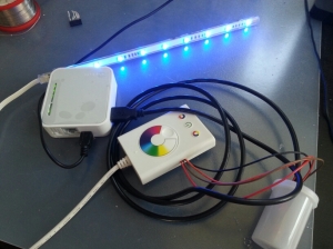
i have created a “WLAN Ikea Dioder”.
You need
- Ikea RGB Dioder
- Arduino pro mini
- Sparkfun FTDI Basic Breakout
- TP-Link TL-MR3020 or TPLink WR703N
- Some Cables
In this article we use the TP-Link TL-MR3020 mini router.
Implementation:
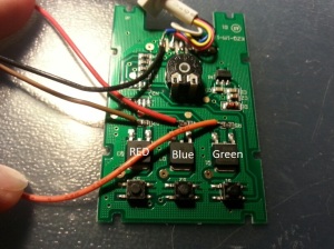
1. “Modify” the Dioder to gain access to the circuit and remove the microcontroller:
2. Install OpenWRT on the TP Link mini Router as described in the OpenWRT Wiki: http://wiki.openwrt.org/toh/tp-link/tl-mr3020
3. Configure the Openwrt as desired but enable ssh access!
4. Execute the following steps on the MR3020:
- Packages:
opkg update
opkg install kmod-usb-serial-ftdi
- Busybox:
Get the Busyboy as described here
After unzipping:
mv busybox /bin/busybox.stty && ln -s /bin/busybox.stty /bin/stty
chmod +x /bin/stty
- “Dioder Script”
place the following code into /www/cgi-bin/dioder then execute
chmod +x /www/cgi-bin/dioder
#!/bin/sh -ax

SP=/dev/ttyUSB0
CMD=";$QUERY_STRING"

RED=`echo "$QUERY_STRING" | grep -oiE "(|[?&])red=[0-9]+" | cut -f 2 -d "=" | head -n1`
GREEN=`echo "$QUERY_STRING" | grep -oiE "(|[?&])green=[0-9]+" | cut -f 2 -d "=" | head -n1`
BLUE=`echo "$QUERY_STRING" | grep -oiE "(|[?&])blue=[0-9]+" | cut -f 2 -d "=" | head -n1`

echo "Content-type: application/json"
echo ""

if [ -z "$RED" ] || [ -z "$GREEN" ] || [ -z "$BLUE" ]; then
    echo "{ 'status': 'error', 'msg': 'missing color' }"
else
        [ "$(stty -F $SP -a | grep speed | cut -d ' ' -f 2)" != "9600" ] && stty -F $SP raw speed 9600 -crtscts cs8 -parenb -cstopb

         if [ "$RED" -gt "255" ]; then
                RED="255"
         fi
         if [ "$GREEN" -gt "255" ]; then
                GREEN="255"
         fi
         if [ "$BLUE" -gt "255" ]; then
                BLUE="255"
         fi

         if [ ${#RED} -lt 3 ]; then
                if [ ${#RED} -eq 2 ]; then
                        RED=0$RED
                fi
                if [ ${#RED} -eq 1 ]; then
                        RED=00$RED
                fi
         fi
         if [ ${#GREEN} -lt 3 ]; then
                if [ ${#GREEN} -eq 2 ]; then
                         GREEN=0$GREEN
                fi
                if [ ${#GREEN} -eq 1 ]; then
                        GREEN=00$GREEN
                fi
         fi
         if [ ${#BLUE} -lt 3 ]; then
                if [ ${#BLUE} -eq 2 ]; then
                        BLUE=0$BLUE
                fi
                if [ ${#BLUE} -eq 1 ]; then
                        BLUE=00$BLUE
                fi
         fi

         CMD=";$RED,$GREEN,$BLUE;"

               echo $CMD > $SP
                    echo "{ 'status' : 'success', 'msg' : 'done' }"
fi
5. Load the following Arduino sketch:
String Input;

int rValue = 0;
int gValue = 0;
int bValue = 0;

int OldRValue = 0;
int OldGValue = 0;
int OldBValue = 0;

int RedStepAmount = 0;
int GreenStepAmount = 0;
int BlueStepAmount = 0;

int currentRed = 0;
int currentGreen = 0;
int currentBlue = 0;

#define rLedPin 9
#define gLedPin 11
#define bLedPin 10
#define STEPS 10

void setup()
{
  pinMode(rLedPin, OUTPUT);
  pinMode(gLedPin, OUTPUT);
  pinMode(bLedPin, OUTPUT);

  analogWrite(rLedPin, 0);
  analogWrite(gLedPin, 0);
  analogWrite(bLedPin, 0);

  Serial.begin(9600);
  Serial.println("Started");
}

void loop()
{
  while (Serial.available())
  {
    delay(3);  //delay to allow buffer to fill
    if (Serial.available() >0)
    {
      char c = Serial.read();  //gets one byte from serial buffer
      if(c  != ';')
      {
        Input += c; //makes the string readString
      }
      else
      {
        ParseInput();
      }

    }
  }

}

void ParseInput()
{
  if (Input.length() == 11)
  {
    rValue=Input.substring(0,3).toInt();
    gValue=Input.substring(4,7).toInt();
    bValue=Input.substring(8,11).toInt();

    Serial.print("Got: ");
    Serial.println(Input);
    Serial.print("Red: ");
    Serial.println(rValue);
    Serial.print("Green: ");
    Serial.println(gValue);
    Serial.print("Blue: ");
    Serial.println(bValue);
    Fade(rValue,gValue,bValue);
  }
   Input="";
}

void Fade(int TargetR, int TargetG, int TargetB)
{

RedStepAmount = (TargetR - OldRValue) / STEPS;
GreenStepAmount = (TargetG - OldGValue) / STEPS;
BlueStepAmount = (TargetB - OldBValue) / STEPS;

currentRed = OldRValue;
currentGreen = OldGValue;
currentBlue = OldBValue;
for (int i = 0; i < STEPS; i++) {
   currentRed += RedStepAmount;
   currentGreen += GreenStepAmount;
   currentBlue += BlueStepAmount;
   setColourRGB(currentRed,currentGreen,currentBlue);
   delay(40);
}
setColourRGB(TargetR,TargetG,TargetB);

OldRValue = TargetR;
OldGValue = TargetG;
OldBValue = TargetB;

if(TargetR == 0 && TargetG == 0 && TargetB == 0)
{
  setColourRGB(0,0,0);
}
}void setColourRGB(unsigned int red, unsigned int green, unsigned int blue) {
  analogWrite(rLedPin, red);
  analogWrite(gLedPin, green);
  analogWrite(bLedPin, blue);
 }
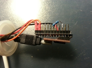
6. Connect the Cables from the Dioder to the arduino pins defined in the sketch and Add an resistor (120 ohm) between 5v and reset to prevent auto reset on serial connection…
7. Connect the arduino to the FTDI Adapter to the MR3020 and call:
http://$mr3020ip/cgi-bin/dioder?RED=000&GREEN=000&BLUE=255
(I love the blue light ;))
If it is not working check if the serial adapter was recognized by the mr3020 with the dmesg command. You should see a message similiar to this:
[ 10.430000] usbserial: USB Serial Driver core
[ 10.480000] USB Serial support registered for FTDI USB Serial Device
[ 10.480000] ftdi_sio 1-1:1.0: FTDI USB Serial Device converter detected
[ 10.490000] usb 1-1: Detected FT232RL
[ 10.490000] usb 1-1: Number of endpoints 2
[ 10.500000] usb 1-1: Endpoint 1 MaxPacketSize 16384
[ 10.500000] usb 1-1: Endpoint 2 MaxPacketSize 16384
[ 10.510000] usb 1-1: Setting MaxPacketSize 64
[ 10.510000] usb 1-1: FTDI USB Serial Device converter now attached to ttyUSB0
If not check your FTDI Adpater and the loaded modules.
NOTE:
If you do not like the “fading” just replace the Fade function in ParseInput() with setColourRGB.
Source:
MR-3020 Busybox and cgi: http://32leav.es/?p=1130
Dioder Hacking: http://hardy.dropbear.id.au/blog/2012/09/hacking-the-ikea-dioder-in-ten-minutes-flat


[…] What’s a links post without some blinky lights? This week we take a look at [Daniel's] hack which connects the Ikea Dioder to a router. […]
[…] What’s a links post without some blinky lights? This week we take a look at [Daniel's] hack which connects the Ikea Dioder to a router. […]
[…] What’s a links post without some blinky lights? This week we take a look at [Daniel's] hack which connects the Ikea Dioder to a router. […]
[…] What’s a links post without some blinky lights? This week we take a look at [Daniel's] hack which connects the Ikea Dioder to a router. […]
[…] What’s a links post without some blinky lights? This week we take a look at [Daniel's] hack which connects the Ikea Dioder to a router. […]
[…] What’s a links post without some blinky lights? This week we take a look at [Daniel's] hack which connects the Ikea Dioder to a router. […]
[…] What’s a links post without some blinky lights? This week we take a look at [Daniel's] hack which connects the Ikea Dioder to a router. […]
[…] What’s a links post without some blinky lights? This week we take a look at [Daniel's] hack which connects the Ikea Dioder to a router. […]